


Summary: In gyratory crusher, the upper frame plays a critical role in stabilizing the main shaft, transferring power, and absorbing heavy impact loads. This article focuses on the upper frame’s structure, core functions, daily maintenance, and the complete standardized replacement procedure for field operators....
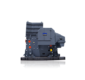
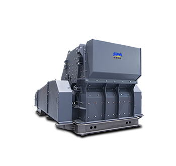
As the premier primary crusher machine for large and extra-large scale mining, aggregate, and mineral processing plants, the gyratory crusher is widely applied in metallurgy, building materials, chemicals, and the cement industry.
The main frame—comprising the upper, middle, and bottom frames—forms the core component of the gyratory crusher. Among these, the upper frame plays a critical role in stabilizing the main shaft, transferring power, and absorbing heavy impact loads. Long-term heavy impact, vibration and dust erosion inevitably cause frame deformation, sealing failure and metal fatigue, making upper frame replacement one of the most essential overhaul works for gyratory crushers.
This article focuses on the upper frame’s structure, core functions, daily maintenance, and the complete standardized replacement procedure for field operators.

1. Structure of Upper Frame Assembly
The upper frame assembly of a gyratory crusher typically consists of four core components: the upper frame, the main shaft bushing, the thrust bearing, and the sealing device.
The upper frame serves as the foundational framework; featuring a high-strength design with cast steel or welded structures, it is built to withstand the massive impact forces generated during the crushing process.
The main shaft bushing acts as a "joint sleeve", utilizing a lubricating layer to minimize friction between the main shaft and the upper frame.
The thrust bearing is to balance the axial forces of the main shaft, preventing component failure and equipment damage caused by unbalanced loads.
The sealing device functions like a "dust shield", blocking dust from entering the internal components and thereby extending their service life.

2. Core Functions of the Upper Frame
In a gyratory crusher, the upper frame primarily serves 5 functions:
2.1 Suspension Support
The top of the upper frame supports a beam. A bushing inside the beam's center bore suspends the crushing cone's main shaft, enabling the gyratory motion of the mantle.
2.2 Fix the Position of the Main Shaft
Through a clearance fit between the main shaft bushing and the upper frame, it prevents radial runout of the main shaft during high-speed and heavy load rotation.
2.3 Transmit Crushing Force
The impact force of raw material in the crushing chamber on the moving cone (mantle) is transmitted through the main shaft to the upper frame and then distributed from the upper frame to the crusher foundation.
2.4 Load Bearing
As a core structural component, the upper frame absorbs the radial and partial axial forces generated during crushing, maintaining the gyratory crusher's geometric alignment.
2.5 Buffer and Absorb Vibrations
The thrust bearing and sealing device work together to absorb a significant portion of vibration energy, preventing the gyratory crusher from experiencing structural fatigue due to long-term vibration.
3. When to Replace the Upper Frame
Before disassembling and replacing the upper frame, operators must evaluate whether replacement is necessary according to equipment operating conditions.
Direct Triggers for Replacement:
- Persistent excessive vibration: Vibration amplitude continuously exceeds 0.1mm after maintenance.
- Structural deformation: Structural damage in the upper frame, such as deformation, cracks or obvious metal fatigue.
- Severe sealing failure: Dust cannot be isolated even after replacing sealing parts repeatedly.
- Poor operational accuracy: Severe wear on connection joints that compromises operational accuracy and cannot be restored through repair.
- Main shaft unstable operation: Eccentric wear of the bushing leads to main shaft wobble.

4. Standard Upper Frame Replacement Procedure
4.1 Pre-Shutdown Preparation
Stop feeding completely, empty all materials inside the crushing cavity, and shut down the equipment. Cut off power and lubrication system, and lock the equipment to ensure construction safety.
4.2 Dismantle Auxiliary Components
Remove external dust covers, sealing assemblies, connecting bolts and lubrication pipelines. Take out the thrust bearing and main shaft bushing in sequence to expose the upper frame.
4.3 Hoist and Remove Old Upper Frame
Use professional hoisting tools to fix the upper frame steadily. Remove all connecting bolts between the upper frame and middle frame, then lift the old frame vertically to avoid collision and friction.
4.4 Install New Upper Frame
Place the new high-strength upper frame in an accurate position. Fasten all bolts evenly in diagonal order to ensure uniform stress distribution.
4.5 Reassemble Internal Accessories
Reinstall the main shaft bushing, thrust bearing and sealing device. Inject sufficient grease to form an intact lubricating layer.
4.6 Post-Replacement Debugging
Perform no-load test operation for 1 to 2 hours. Monitor vibration data, temperature and running sound. If the vibration amplitude is controlled within 0.1mm and no abnormal noise occurs, formal feeding production can be resumed.

5. Daily Maintenance to Extend Upper Frame Service Life
To avoid frequent replacement and reduce maintenance costs, operators must adhere to the following daily maintenance routine:
5.1 Regular Lubrication
Replenish the main shaft bushing with grease every 8 hours to prevent dry friction and temperature rise.
5.2 Weekly Seal Inspection
Inspect rubber sealing elements weekly for degradation or aging. Early replacement prevents dust ingress and internal wear.
5.3 Real-time Vibration Monitoring
Leverage vibration sensors to monitor the upper frame in real time. If the vibration amplitude exceeds 0.1mm, shut down the gyratory crusher immediately for inspection.
5.4 Strict Overload Prevention
Overfeeding will significantly increase upper frame pressure and accelerate metal fatigue. Feeding capacity must not exceed the gyratory crusher’s rated processing volume.
6. SBM HGT Gyratory Crusher Upper Frame Advantages
SBM's HGT gyratory crusher features a high-strength, extra-heavy-duty upper frame design, delivering superior overall structural strength. The optimized casting process enhances rigidity and impact resistance, effectively reducing deformation and replacement frequency.
Built to withstand the harshest production conditions, it ensures longer service life, safer and more reliable operation, and reduced overall production and maintenance costs.