






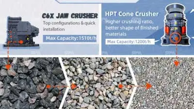

When the final aggregate is sent for testing, the gradation meets the specification and the fines content is acceptable, yet the flakiness content exceeds the limit — a problem that occurs regularly on some production lines.
Elongated and flaky particles are particles that are slender or flat in shape. Most standards limit the proportion of such particles according to the intended use of the aggregate, with requirements for concrete aggregate typically stricter than those for road base fill. Under load, elongated and flaky particles tend to break along their long axis and show clear weaknesses during mixing and load bearing, which is why every specification lists them as a controlled parameter.
To control the flakiness content of aggregate, the first step is to understand where it comes from.
Get Solutions to Aggregate Flakiness Problems


I. Why the Flakiness Content of Aggregate Is Too High
There is more than one cause, and they differ in how easily they can be controlled. The first step is to distinguish how particles are broken inside the crushing chamber, because the shape after crushing is determined by this.
Click Here to Get Solutions to Aggregate Flakiness Problems
1.1 Single-Particle Crushing, Inter-Particle Breakage, and Impact Crushing
On an aggregate line, the way particles are broken can be grouped into three types.
Single-particle crushing: a particle is held and loaded individually between two working surfaces. Because a particle contains weak planes of different orientations, individual loading causes it to split along its weakest plane, producing flat, straight, and narrow fracture surfaces. Particles that repeatedly undergo this type of breaking become elongated strips or flat flakes. This is the main source of elongated and flaky particles.
Inter-particle breakage: when the crushing chamber is filled with material, each particle is surrounded by other particles; particles press against one another, the loading directions are dispersed and evenly distributed, and the product approaches a cubical shape. A cone crusher operating under choke-feeding conditions works in this manner.
Impact crushing: a particle is struck by a high-speed rotating component or thrown against the liners; loading concentrates at the moment of impact, and the product has sharp, well-defined edges and approaches a cubical shape. Impact crushers and vertical shaft impact crushers work in this manner.
The flakiness content of a line is the result of how much each of the three breaking modes contributes: the higher the share of single-particle crushing, the higher the flakiness content.
1.2 Equipment Type: Compression-Type and Impact-Type
Crushing equipment falls into two major categories by breaking mode. Compression-type crushers break material by the gradual approach of two working surfaces; jaw crushers and cone crushers belong to this category. Impact-type crushers break material by striking it with high-speed rotating components; impact crushers and VSI crushers belong to this category.
In SBM's aggregate crushing product line: compression-type equipment handles primary and medium-fine crushing, impact-type equipment handles medium-fine crushing and final shaping, and shaping is performed by the VSI crusher. The ratio of the two equipment categories on a line determines how much each of the three breaking modes contributes.
Click Here to Get Solutions to Aggregate Flakiness Problems
For compression-type equipment to produce good particle shape, the prerequisite is that the chamber is filled with material so particles undergo inter-particle breakage rather than degrading into single-particle crushing. With the same cone crusher, different feeding conditions can produce noticeably different product shapes.

1.3 Feeding Condition: Chamber Level Determines How Particles Are Broken
The same cone crusher produces different product shapes when the chamber level is sufficient versus insufficient.
When the chamber level is sufficient (i.e., choke feeding), material fills the crushing chamber, breaking occurs between particles, and product shape is good. When the level is insufficient, material falls directly into the open space between the liners, breaking degrades into single-particle crushing, and the flakiness proportion rises accordingly.
Feeding also needs to be uniform. When material concentrates along one side of the chamber, one side is choke-fed while the other runs empty; the breaking conditions on both the loaded side and the empty side deviate from the design state simultaneously, and particle shape and liner wear deteriorate together.
1.4 Crushing Ratio: One Stage Carrying Too Much Compression
The crushing ratio is the ratio of a stage's feed size to its discharge size, reflecting how much that stage compresses the material.
When the total crushing ratio is distributed across several stages, the compression in each stage is limited; particles undergo multiple small compressions inside the chamber, and particle shape is easy to control. When a two-stage flow produces the final product directly and the total crushing ratio concentrates in the last stage, the discharge opening of that stage must be set very small; every particle undergoes one large compression, and elongated particles and fines increase at the same time.
At this point, the stage arrangement needs to be adjusted to reduce the flakiness content.
Get Solutions to Aggregate Flakiness Problems
1.5 Chamber Profile and Wear: Settings Drift Gradually with Operation
The chamber profile determines how many compressions a particle undergoes inside the chamber and along what path it travels, and must be selected according to material hardness and product requirements.
The settings at commissioning will not hold indefinitely. As the liners wear, the chamber profile drifts and the actual discharge opening enlarges; operators then reduce the discharge opening to maintain the product size, compression concentrates again in individual zones, and breaking reverts to single-particle crushing. The whole process is gradual — parameters deteriorate slowly with operating hours and are often mistaken for a change in the material.
1.6 The Material Itself
Rocks with well-developed bedding, such as shale and slate, contain natural weak planes inside; they split along the bedding during crushing, and the flakiness proportion runs high. When the indicator rises after a change of quarry face or material source — with the same machine and the same settings — the cause lies in the material.
II. How to Solve High Flakiness Content
2.1 Step One: Confirm the Testing Standard and Sampling Location
Before adjusting equipment, first confirm: under which standard the value is measured, which size fraction is counted, and whether the sample is taken from the product stockpile or the conveyor belt. Different standards apply different determination methods (for example, the determination methods for flakiness content in Chinese, European, and American standards differ from one another), and the values cannot be converted directly; different sampling locations also yield different results.
2.2 Step Two: Restore Choke Feeding and Uniform Material Distribution
The first adjustment is feeding. It involves no flow modification and no spare-part replacement, can be implemented on site, and shows results most directly.
Specifically: verify that the conveying capacity of the feeding equipment matches the crusher throughput; install a buffer hopper before medium crushing if necessary to stabilize feeding continuity; adjust the material distribution device so that material spreads evenly across the chamber width. After the adjustment, check whether the crusher power stabilizes in a higher range — this confirms that choke feeding has been established.
2.3 Step Three: Redistribute the Crushing Ratio
If feeding has been restored but the indicator still exceeds the limit, work down through the crushing ratios of each stage.
Three feasible paths exist: redistribute the total crushing ratio across the stages; convert a two-stage flow into three stages; or add a closed circuit with check screening to the medium-fine crushing stage so that screen oversize returns for re-crushing, reducing the compression load on the final stage accordingly.
Click Here to Get Solutions to Aggregate Flakiness Problems

2.4 Step Four: Calibrate Chamber Profile, Discharge Opening, and Wear Parts
Once the crushing ratio distribution is set, the chamber profile and discharge opening of each stage must be matched accordingly: the chamber profile is selected according to material hardness and product shape requirements, and the discharge opening is re-verified against its setting.
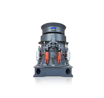
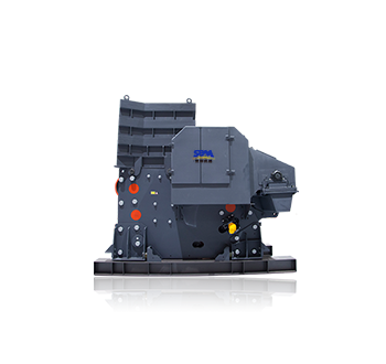
The chamber profile can be changed without replacing the whole machine. SBM's HPT cone crusher works primarily through inter-particle breakage; changing the liners allows switching between coarse and fine chambers, making it easy to re-match the machine to product shape requirements.
Wear parts management is a supporting task. Liners should be replaced promptly once wear begins to affect the chamber profile. Only when both settings and wear are under control can particle shape remain stable over the long term.
2.5 Step Five: Add a Shaping Stage
If all the measures above are in place and the indicator is still too high, treatment must move to the flow level: add a shaping operation before product screening.
The goal of shaping is to correct particle shape, so equipment selection differs from that of crushing stages: the VSI crusher works by impact crushing and yields a cubical product; the impact crusher combines crushing and shaping functions and suits soft to medium-hard materials.
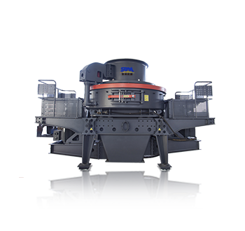
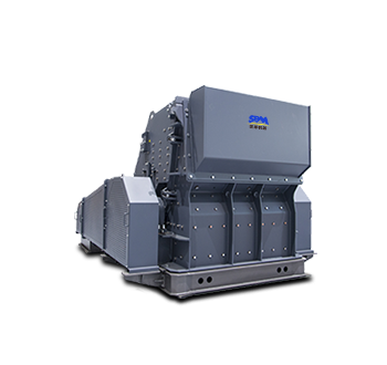
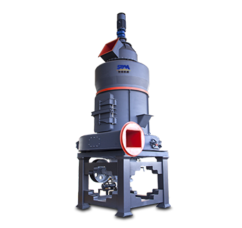
SBM's VSI6X vertical shaft impact crusher, a dedicated sand making and shaping machine, operates in a rock-on-rock mode and is widely used for aggregate shaping; SBM's CI5X impact crusher features an involute crushing chamber, produces a cubical product with low flakiness, and suits soft and medium-hard materials. The choice between the two depends on material hardness and the strictness of the limit.
A shaping stage increases the proportion of fines produced, so it must form a closed circuit with check screening to screen out qualified size fractions promptly and prevent qualified particles from being repeatedly impacted inside the chamber and over-crushed.
Click Here to Get Solutions to Aggregate Flakiness Problems
III. FAQ
Q: What is the limit for flakiness content?
A: It is determined by the intended use of the aggregate and the standard applied. For the same batch of material, the applicable limit differs between concrete structural use and road base fill; determination methods also differ across standards, and the values cannot be converted directly. The standard version cited in the design documents and the contract should govern.
Q: A cone crusher is producing too many flaky particles — is it the machine's fault?
A: Check the feeding condition first, then the operating settings. When the chamber level is insufficient, breaking degrades into single-particle crushing, and restoring choke feeding improves the situation; if the level is normal but the indicator remains high, check in turn the crushing ratio distribution, the chamber profile matching, and the liner wear. Only after settings and wear have both been ruled out does it become necessary to assess whether the equipment type matches the product shape requirement.
Q: Can reducing the discharge opening lower the flakiness content?
A: The effect is limited. After the discharge opening is reduced, the compression per stage increases; particles undergo single-particle crushing at a higher compression, the flake proportion rises, and at the same time throughput drops and the circulating load increases. To improve particle shape, start with the feeding condition and the crushing ratio distribution.
Q: Which produces better particle shape, an impact crusher or a cone crusher?
A: It depends on the material. An impact crusher breaks material by impact, yielding a cubical product with low flakiness, and suits soft to medium-hard materials; a cone crusher works primarily through inter-particle breakage, handles high-hardness and highly abrasive materials, and its product shape depends on choke feeding and chamber profile matching. Judge material hardness and abrasiveness first, then the shape requirement.
Q: When is a shaping stage needed?
A: When feeding, crushing ratio, chamber profile, and wear parts are all in place and the indicator is still too high. The shaping stage is arranged before product screening and forms a closed circuit with check screening; after shaping, the fines proportion rises, so qualified size fractions must be screened out promptly.
Conclusion
Excessive flakiness content is never a parameter problem of a single machine; it is the combined result of feeding, crushing ratio, chamber profile, wear parts, and flow configuration, and can be investigated layer by layer in the order given above.
SBM's aggregate crushing product line covers primary crushing, medium-fine crushing, shaping, and screening, and can be combined into a complete line according to material and product requirements. For particle shape problems on existing production lines, SBM provides material testing, flow calculation, and retrofit and upgrade solutions, along with full-process technical support and services for the production line.
If your production line is troubled by excessively high flakiness content, contact the SBM process team for solutions and recommendations.
Get Solutions to Aggregate Flakiness Problems


 Get Solution
 Send Message
